In this tutorial we will be going over how to configure In-Band management for APIC and fabric switches. In this tutorial specifically we will be overviewing the necessary configuration where endpoints outside of ACI (via an L3Out) need to access the APIC, leaves, and spines using their In-Band Management IPs.
Prerequisites:
* Fabric Discovery Completed
* Understanding of ACI Access Policies
* Understanding of ACI Contracts
* Already Configured and Operational L3Out
* Understanding of L3Out External Network Instance Profile (External EPG) Configuration
My Setup:
* Running ACI version 3.2(6i)
* Topology:

Topics:
* Configuring In-Band Access Policies
* Configuring mgmt Tenant Policies
* Configuring Contract in the common Tenant
* Applying the Contract to In-Band EPG and L3Out External EPG
Configuring In-Band Access Policies:
Before we get started in the actual Access Policy configuration, below is a high level overview of the Access Policy objects and object names we’ll be using for our leaf to APIC fabric connections:

The first step in the In-Band Management configuration is to create all the necessary Access Policies for your leaf fabric interfaces which connect to your APICs. In my setup leaf1 and leaf2 are connected to apic1, apic2, and apic3 using interfaces Eth1/1-3 (seen in the topology towards the top of this tutorial).
The first step in Access Policy configuration is to configure a Leaf Profile. To configure a Leaf Profile navigate to the following APIC web GUI path:
Fabric -> Access Policies -> Switches -> Leaf Switches -> Profiles

Right click Profiles and select Create Leaf Profile
From here we’ll assign a name to our Leaf Profile as well as select the leaves we want to be associated to our Leaf Profile. For our purposes we’ll name our Leaf Profile Leaf-101-102-In-Band-LeafProf since only leaf1 (101) and leaf2 (102) are the only leaves connected to my APICs.

Click Next and Finish to skip the interface Associations, we’ll come back to this later. Our next step is to create the Leaf Interface Profile.
We can create the Leaf Interface Profile directly from the Leaf Profile page by clicking the + sign in the Associated Interface Selector Profiles region:

Or we can navigate to the following APIC web GUI path:
Fabric -> Access Policies -> Interfaces -> Leaf Interfaces -> Profiles

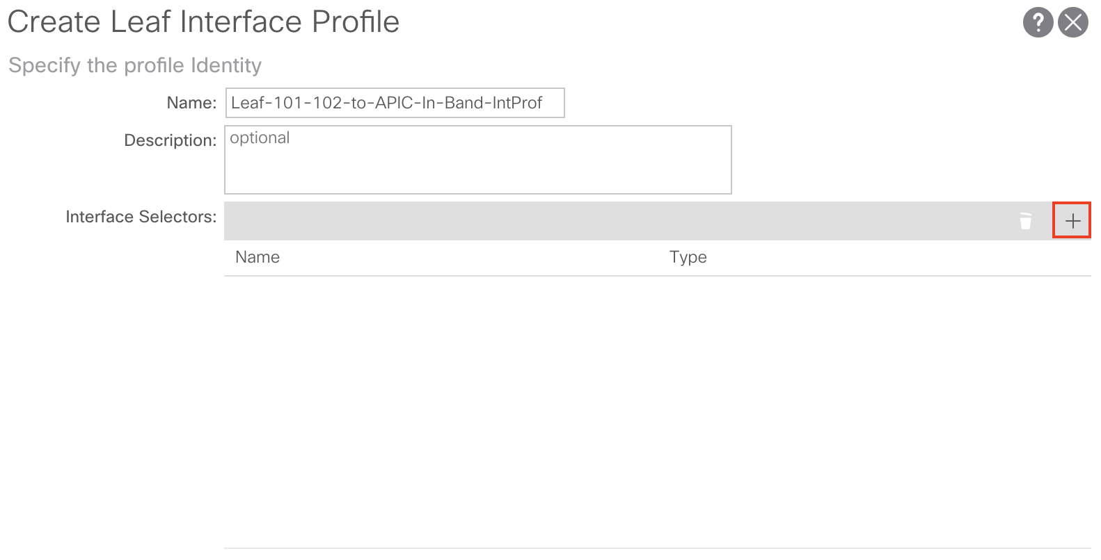
Right click Profiles and select Create Leaf Interface Profile
For our purposes we’re going to name our Leaf Interface Profile Leaf-101-102-to-APIC-In-Band-IntProf:

The next step is to create a Leaf Interface Selector to signify what particular leaf interfaces are connected to our APICs.
We can create the Leaf Interface Selector directly from the Create Leaf Interface Profile window by clicking the + sign:
Or you can navigate to the following APIC web GUI path:
Fabric -> Access Policies -> Interfaces -> Leaf Interfaces -> Profiles -> YOUR_LEAF_PROFILE_HERE
Right click YOUR_LEAF_PROFILE_HERE and select Create Access Port Selector
From here we’ll assign a Name, Interface ID, and Interface Policy Group. For our configuration we’ll name our Leaf Interface Selector Leaf-101-102-to-APIC-In-Band-IntSelect, use 1/1-3 as our Interface ID, and create a new Interface Policy Group:

You can create the Interface Policy Group directly from the Create Access Port Selector window by clicking the dropdown list and selecting Create Leaf Access Port Policy Group:

Or you can navigate to the following APIC web GUI path:
Fabric -> Access Policies -> Interfaces -> Leaf Interfaces -> Policy Groups -> Leaf Access Port

Right click Leaf Access Port and select Create Leaf Access Port Policy Group
From here we’ll assign a name to our Access Port Policy Group of In-Band-PolicyGroup create an LLDP Policy and create an Attached Entity Profile (AEP):

You can create the LLDP Policy directly from the Create Leaf Access Port Policy Group window by clicking the dropdown list and selecting Create LLDP Interface Policy:

Or you can navigate to the following APIC web GUI path:
Fabric -> Access Policies -> Policies -> Interface -> LLDP Interface
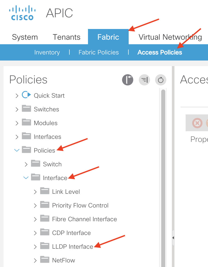
Right click LLDP Interface and select Create LLDP Interface Policy
For our purposes we’ll name our LLDP Interface Policy LLDP-Enabled and set the Receive State and Transmit State to Enabled:

Click Submit to save and apply your configuration
Next, we’ll need to create and associate an Attached Entity Profile (AEP) to our Access Port Policy Group. You can create the Attached Entity Profile directly from the Create Leaf Access Port Policy Group window by clicking the dropdown list and selecting Create Attachable Access Entity Profile:

Or you can navigate to the following APIC web GUI path:
Fabric -> Access Policies -> Policies -> Global -> Attachable Access Entity Profiles

Right click Attachable Access Entity Profiles and select Create Attachable Access Entity Profile
From here we’ll assign a name to our AEP and create a Physical Domain. For our purposes we’ll name our AEP In-Band-AEP:

You can create the Physical Domain by clicking the + sign and selecting Create Physical Domain from the drop down list:

Or you can navigate to the following APIC web GUI path:
Fabric -> Access Policies -> Physical and External Domains -> Physical Domains

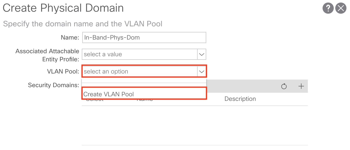
Right click Physical Domains and select Create Physical Domain
From here we’ll assign a name to our Physical Domain and create a VLAN Pool. For our purposes we’ll name our Physical Domain In-Band-Phys-Dom:

Note: You do not need to create/associate an AEP from the Create Physical Domain window
You can create the VLAN Pool by clicking the dropdown list and selecting Create VLAN Pool:
Or you can navigate to the following APIC web GUI path:
Fabric -> Access Policies -> Pools -> VLAN

Right click VLAN and select Create VLAN Pool
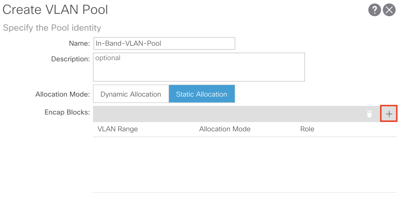
From here we’ll assign a name to our VLAN Pool, set the Allocation Mode to Static, and add an Encap Block for the single VLAN we want to dedicate to use for In-Band management. For our purposes we’ll name our VLAN Pool In-Band-VLAN-Pool:

As mentioned we’ll set the Allocation Mode to Static. We’ll also need to add our Encap Block for the In-Band management VLAN we want to use. To do so, click the + sign to add your desired VLAN:
From here we’ll add our desired VLAN, set the Allocation Mode to Static and set the Role to External or On the wire encapsulations. For our purposes we’ll use VLAN 10 for our In-Band management VLAN:

Click OK and Submit until all of your changes are saved
This concludes all the necessary Access Policies for In-Band Management.
Configuring mgmt Tenant Policies:
The next step in configuring In-Band management is to create/configure the necessary policies in the mgmt tenant.
To do so navigate to the following APIC web GUI path:
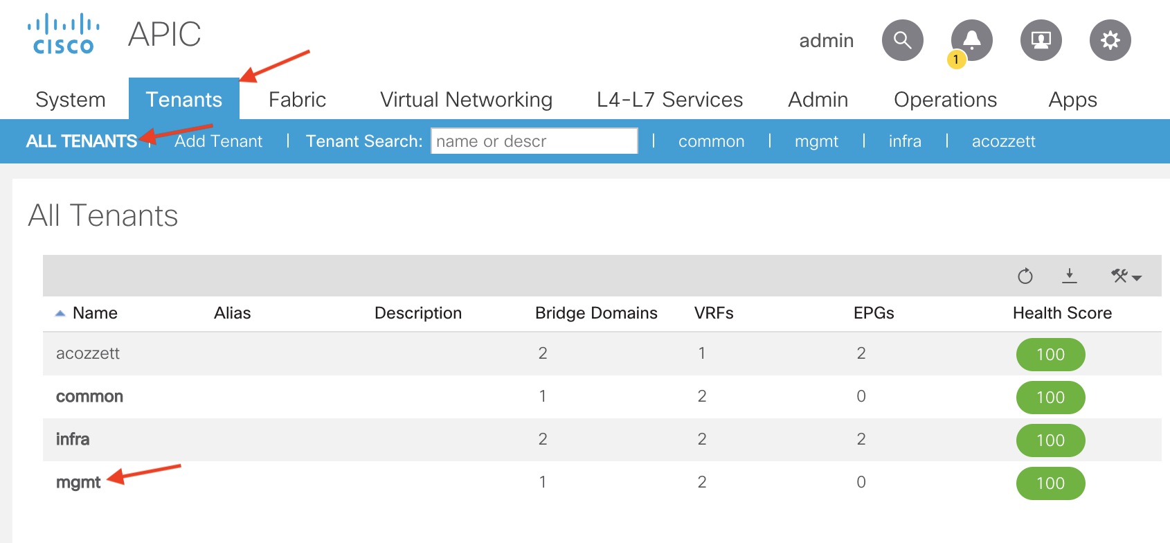
Tenant -> ALL TENANTS -> mgmt
The first configuration step when in the mgmt tenant is to define our In-Band Bridge Domain. The purpose of this In-Band Bridge Domain is to define what subnet we want to use for our In-Band IPs we are going to allocated to our APICs, leaves, and spines.
By default ACI will come with a Bridge Domain named inb which will be configured to use the inb VRF, which is also included out of the box. For our purposes we are going to use the default inb Bridge Domain. So let’s go ahead and define what subnet we want to use for In-Band Management in our inb Bridge Domain.
Note: If you want to create your own Bridge Domain to use for In-Band Management, use the inb VRF which is located under the following APIC web GUI path:
Tenants -> mgmt -> Networking -> VRFs

To configure the In-Band Management subnet under the inb Bridge Domain navigate to the following APIC web GUI path:
Tenants -> mgmt -> Networking -> Bridge Domains -> inb

From here, in the right-hand panel we’ll select the Policy tab and L3 Configurations tab:

Now let’s go ahead and add our subnet for In-Band Management. To do so, click the + sign in the Subnets region:

For our purposes I’m going to assign a subnet of 192.168.10.254/24 to use for In-Band Management. 192.168.10.254 will be the gateway for this network. Since my outside network (L3Out) needs to reach these In-Band IP addresses I will mark the subnet as Advertise Externally. Additionally since my inb Bridge Domain is tied to my inb VRF and my L3Out is tied to a different VRF in my user tenant, I will need to mark the subnet as Shared Between VRFs. This will allow the 192.168.10.0/24 subnet to be leaked from the inb VRF to my user tenant VRF my L3Out is using.
Our configuration for the inb Bride Domain subnet will look like such:

Click Submit to save and apply your configuration
The next configuration step in the mgmt tenant is to create our In-Band EPG. To create the In-Band EPG navigate to the following APIC web GUI path:
Tenant -> mgmt -> Node Management EPGs

Right click Node Management EPGs and select Create In-Band Management EPG
From here we’ll assign a Name to our new In-Band management EPG, assign an Encap VLAN, and create a Bridge Domain which will contain the subnet we want to allocate to our In-Band IPs.
For our purposes we’ll assign a name of In-Band-EPG and use an Encap value of vlan-10 (which is the VLAN which we configured earlier in our VLAN Pool named In-Band-VLAN-Pool). We’ll also associate our inb Bridge Domain which we defined the 192.168.10.254/24 subnet under earlier. Our configuration will look like such:
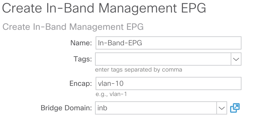
Click Submit to save and apply your configuration
Next, we’ll start assigning In-Band IP addresses to our APICs, leaves, and spines. To do so navigate to the following APIC web GUI path:
Tenants -> mgmt -> Node Management Addresses -> Static Node Management Addresses:

Right click Static Node Management Addresses and select Create Static Node Management Address
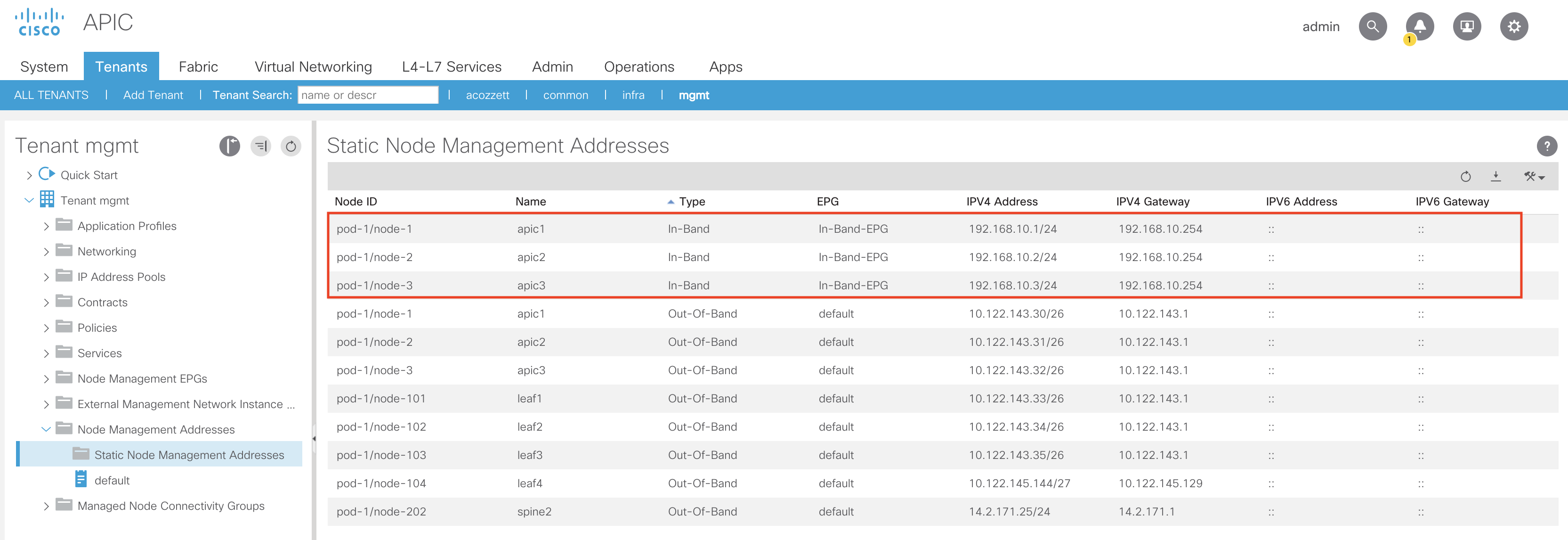
From here we’ll go ahead and input the Node ID(s) that we want to assign an In-Band Management IP. For our purposes I’m going to assign In-Band Management IPs to our 3 APICs (node ID’s 1-3) and our leaves and spines. We’ll also select our In-Band-EPG that we created earlier, and assign an In-Band IP address that is in the same subnet as the subnet we defined under the inb Bridge Domain. We’ll also assign the gateway address using the same IP as the one we defined under the inb Bridge Domain (192.168.10.254). Our configuration will look like such for our APICs:
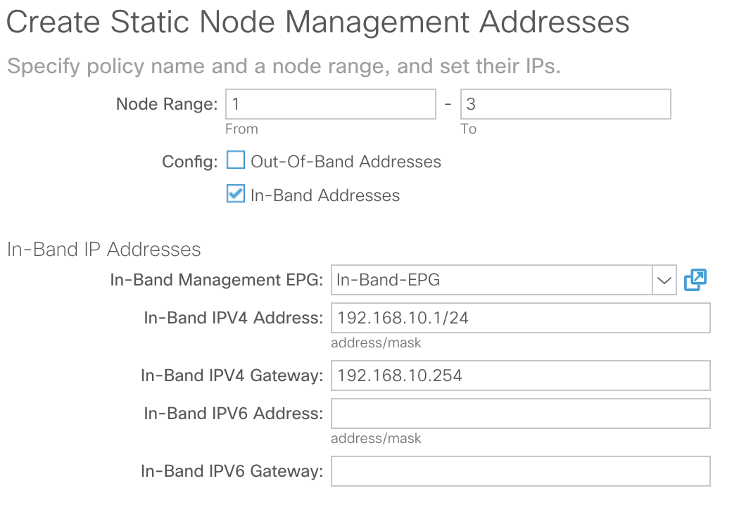
The above configuration will assign 192.168.10.1 to APIC-1, 192.168.10.2 to APIC-2, and 192.168.10.3 to APIC-3.
Click Submit to save and apply your configuration.
The below pop-up box will appear informing you that management traffic will be switched to In-Band:

Depending on your APIC Connectivity Preferences, the routing table on the APICs will change. To verify your APIC Connectivity Preferences navigate to the following APIC Web GUI Path:
System -> System Settings -> APIC Connectivity Preferences
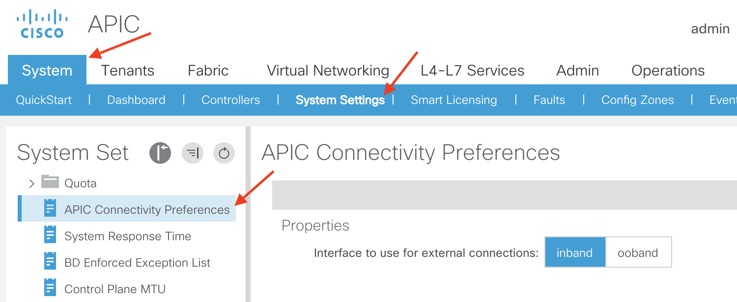
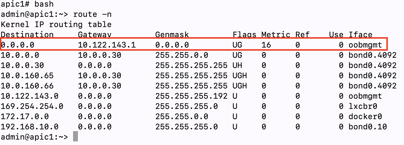
From the above screenshot we can see that currently the APIC Connectivity Preference is set to inband. If we verify the routing table on our APICs we can see that even though inband is configured for the APIC Connectivity Preference the default route on my APICs is pointing to a gateway configured for my Out-Of-Band network (10.122.143.1) since we haven’t fully submitted the configuration for the In-Band IPs/Gateway:
APIC Connectivity Preference Set to ‘inband’ But No In-Band IP Configured:
Once we click Yes on the management change to In-Band pop-up box, we will see that the preferred gateway for a default route is changed to the In-Band gateway we are configuring:
APIC Connectivity Preference Set to ‘inband’ And In-Band IP Configured:

Note: This default route on the APICs is important for traffic that is originated from the APIC itself. One example of traffic that originates from an APIC is AAA authentication (TACACS, RADIUS, LDAP, etc). For this traffic type the APIC is the originator of the traffic. If you have AAA servers that are reachable from the APIC using Out-of-Band management and the APIC Connectivity Preference is set to inband and you configure an In-Band IP on your APICs, you will lose connectivity to your AAA server. To maintain connectivity to your AAA server , you will need to set your APIC Connectivity Preference to ooband (if your AAA server is reachable via Out-of-Band) or ensure your AAA server is reachable via In-Band:
APIC Connectivity Preference Set to ‘ooband’ And In-Band IP Configured:

Even if your APIC Connectivity Preference set to ooband and your have In-Band IPs configured, you will still be able to access the In-Band IPs of your APICs since the In-Band traffic is not initiated from the APIC itself. Traffic ingressing an interface on the APIC will egress out the same interface.
After your configuration is submitted you will see your newly configured In-Band IPs configured under the Static Node Management Addresses section of the APIC GUI:
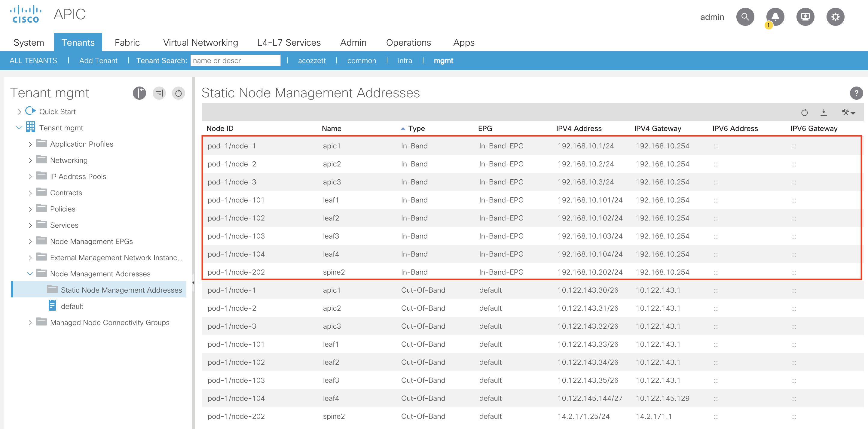
Let’s add the remainder of the In-Band IPs for the leaves and spines:
You can verify the In-Band IP programming on the APICs, leaves and spines by performing the following:
On APIC:
Running the ifconfig command will display a newly created bond0 interface with your In-Band VLAN appended. In our case our bond0 interface for In-Band will be bond0.10 since we are using VLAN-10 for In-Band:
apic1# ifconfig
<trimmed>
bond0.10: flags=4163<UP,BROADCAST,RUNNING,MULTICAST> mtu 1496
inet 192.168.10.1 netmask 255.255.255.0 broadcast 192.168.10.255
inet6 fe80::5e83:8fff:fe3e:3665 prefixlen 64 scopeid 0x20<link>
ether 5c:83:8f:3e:36:65 txqueuelen 1000 (Ethernet)
RX packets 3 bytes 138 (138.0 B)
RX errors 0 dropped 0 overruns 0 frame 0
TX packets 5570 bytes 235791 (230.2 KiB)
TX errors 0 dropped 0 overruns 0 carrier 0 collisions 0
<trimmed>
On Leaf/Spine:
Running the show vrf command on our leaves and spines shows the inb VRF was pushed:
leaf2# show vrf
VRF-Name VRF-ID State Reason
black-hole 3 Up —
management 2 Up —
mgmt:inb 5 Up —
overlay-1 4 Up —
Running the show ip interface brief vrf mgmt:inb command we can see the In-Band IP we assigned to leaf2 (node-102):
leaf2# show ip interface brief vrf mgmt:inb
IP Interface Status for VRF “mgmt:inb”(5)
Interface Address Interface Status
vlan14 192.168.10.102/24 protocol-up/link-up/admin-up
Note: The In-Band VLAN in the above output for the leaf switch (in my case vlan14) is not guaranteed to be the same VLAN number as what you assigned to be used for In-Band (in my case VLAN-10). That VLAN # can also be different across leaf and spine switches since it is only locally significant to the switch
Now that we’ve assigned the In-Band Management IPs to our desired nodes we’ll need to create the contract to allow traffic from our L3Out to the In-Band IPs. Additionally the contract will perform the route leaking from the inb VRF to our L3Out VRF in our user tenant and vice versa.
Configuring Contract in the common Tenant:
Since our In-Band EPG is in the mgmt tenant and our L3Out is in the user tenant we’ll need to create the contract in the common tenant. That way both the mgmt tenant and the user tenant can see the contract and provide and consume it accordingly.
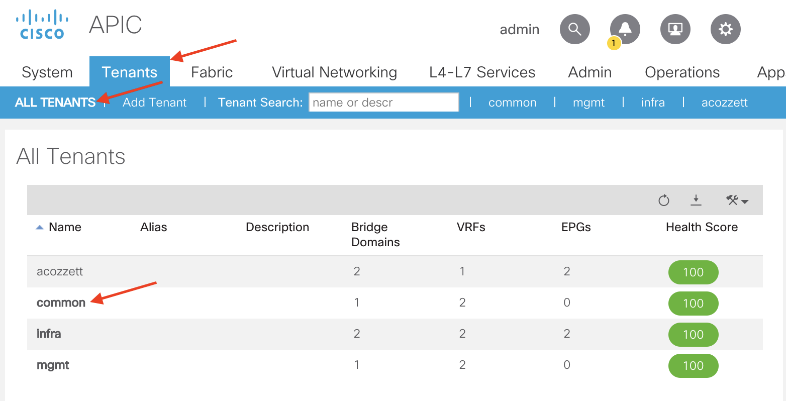
To get to the common tenant navigate to the following APIC web GUI path:
Tenants -> ALL TENANTS -> common
Once in the common tenant navigate to the following APIC web GUI path to create a contract:
Tenant -> common -> Contracts -> Standard

Right click Standard and select Create Contract

In the Create Contract pop-up we’ll need to provide a name, set the Scope of the contract, and create a Contract Subject.
For our purposes we’ll name our contract In-Band-Allow-Contract, set the Scope to Global (since we need to leak routes between two different VRFs across two different tenants). To create the Contract Subject click the + sign in the Subjects region:

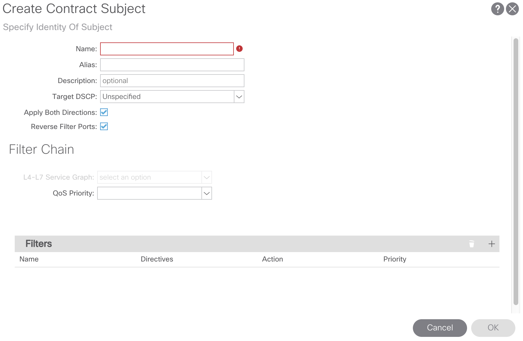
From here we’ll assign a name to our Contract Subject and create a Contract Filter. For our purposes we’ll call our Contract Subject In-Band-Allow-Subject. To create the Contract Filter click the + sign in the Filters region, select the drop-down arrow, and click the + sign to create a Contract Filter:

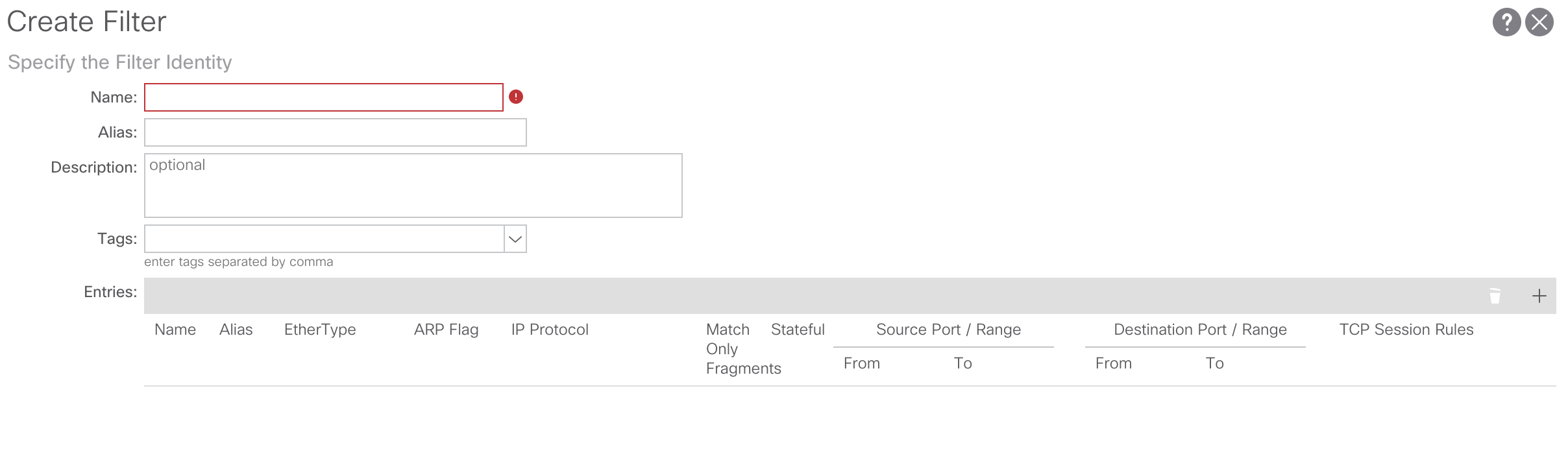
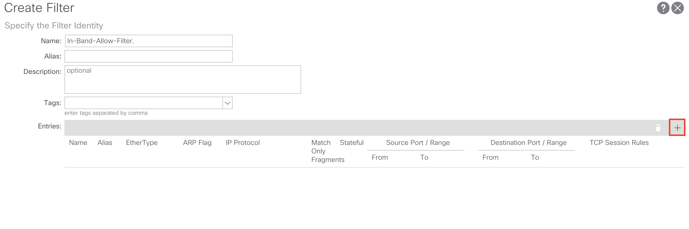
From here we’ll assign a name to our Contract Filter and add a Contract Filter entry. For our purposes we’ll call our Contract Filter In-Band-Allow-Filter. To create the Contract Filter entry click the + sign in the Entries region and create the Contract Filter Entry:

For our purposes I’m just going to create a Contract Filter Entry to allow all traffic to my In-Band EPG. It will look like such:

Click Update and Submit to save and apply your configuration changes.
After the contract configuration is complete we’ll need to apply our newly created contract to our In-Band-EPG in the mgmt tenant as well as our L3Out in our user tenant.
Applying the Contract to In-Band EPG and L3Out External EPG:
First let’s apply our contract configurations to the In-Band-EPG in the mgmt tenant. Navigate back to the mgmt tenant by going to the following APIC web GUI path:
Tenant -> ALL TENANTS -> mgmt
From here we’ll navigate to the the Node Management EPGs and select our In-Band-EPG we created earlier:

From here, in the right-hand panel select the Policy tab and scroll down until you see the region where you can provide and consume a contract:
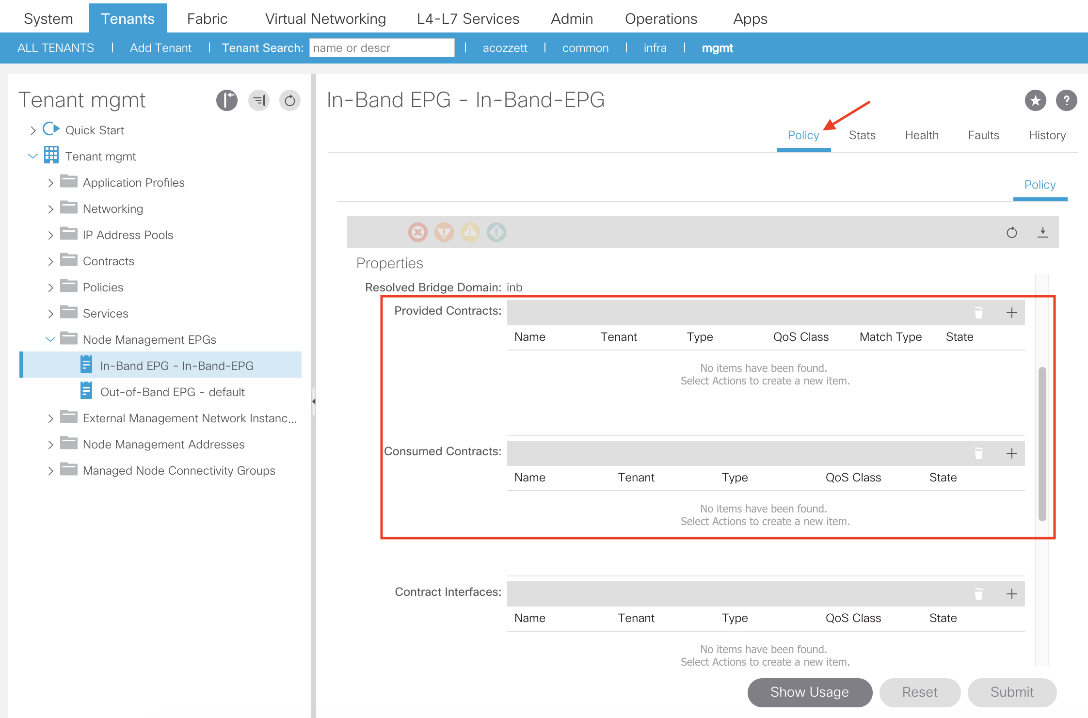
For our purposes we are going to both provide and consume the In-Band-Allow-Contract we created earlier on our In-Band-EPG. To do so, click the + sign in the Provided Contracts and Consumed Contracts region:

From here we’ll select our contract from the drop down list and click Update. Perform this step until the contract is being provided and consumed:


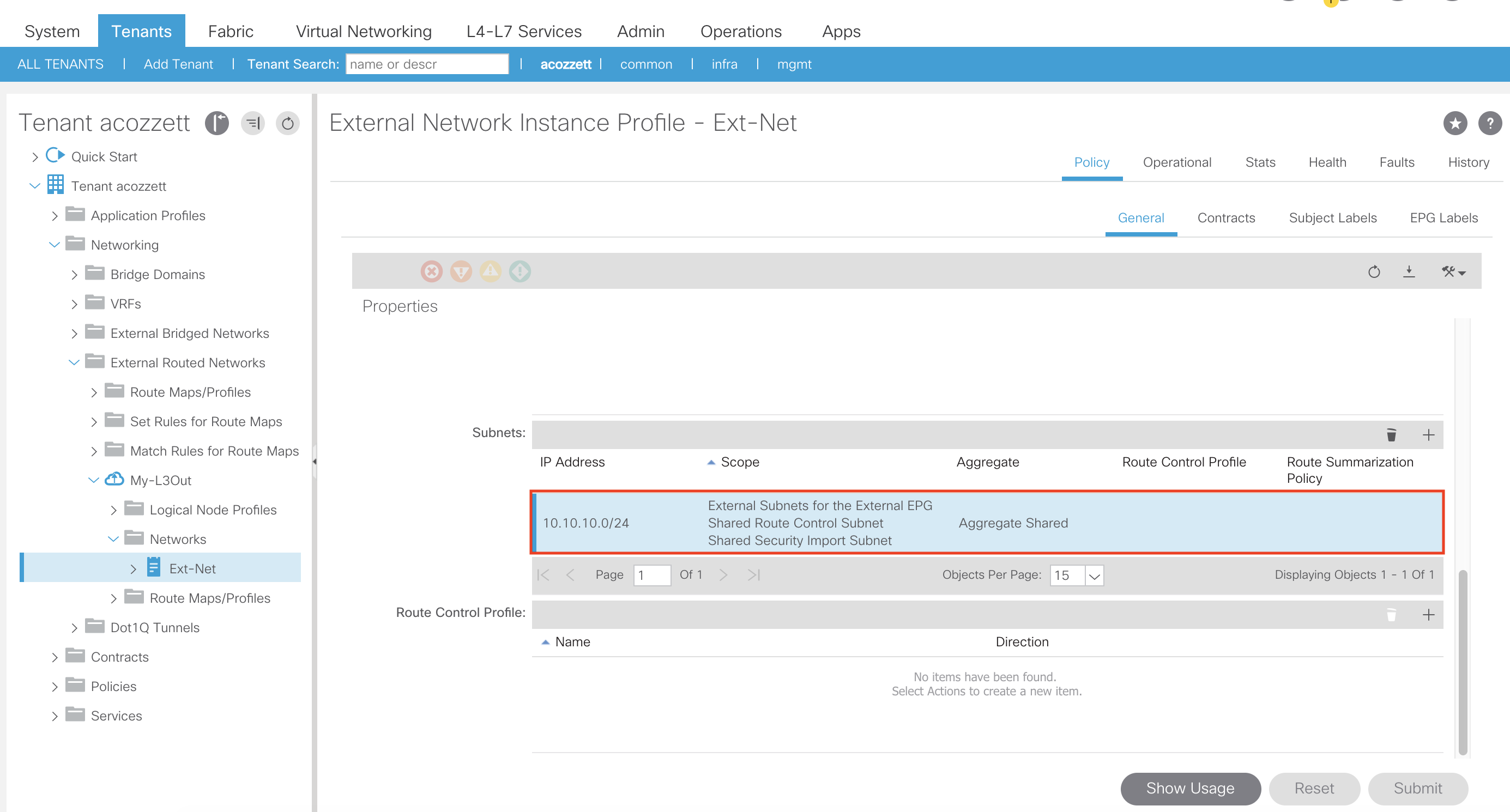
The next step is to apply the contract as a provider and consumer on our L3Out External Network Instance Profile (External EPG):

Additionally, since our L3Out and In-Band Management EPG is using a different VRF we need to apply the necessary flags (External Subnets for the External EPG, Shared Route Control Subnet, Shared Security Import Subnet, and Aggregate Shared [if you need to use it]) on our L3Out External Network Instance Profile subnet to share routes from the L3Out VRF to the inb VRF as well as apply policy to the traffic:
This concludes all the necessary configuration for getting In-Band Management to work in your ACI fabric when using an L3Out. If using a regular EPG instead of an External L3Out EPG, the configuration would be similar. You would just provide and consume the contract on the EPG itself and mark the EPG/BD subnet as Shared Between VRFs to leak the EPG/BD subnet to the inb VRF.

Thanks for this interesting post! What I miss is the connection between the physical and logical side. Where is the relationship between the domain and the In-Band EPG?
LikeLike
Hey Oliver! This is a great question. So there is actually not a place to associate the domain created in the access policies to the In-Band EPG under the “mgmt” tenant. This goes against traditional EPG domain relationships.
I know in early versions of ACI code putting the domain under a traditional EPG was not required (possible it’s still not really required today). The VLANs would still get pushed to the appropriate leaf interfaces, however you would get a nasty F0467 fault under that EPG. There’s actually a newish fabric wide setting in ACI called “Enforce Domain Validation” which makes it so that you need to associate a domain to a regular EPG in order to push VLANs:
“Enforcing Domain Validation restricts EPG VLAN usage by ensuring that the respective Domain & VLAN Pool are bound to the EPG. This prevents accidental or malicious programming of EPGs to use VLAN IDs they may not be permitted to use. Tenant Admins (responsible for Application level policies) typically have different permissions than the Infrastructure Admin (responsible for networking & external connectivity) in ACI – and with this separation of roles you can have one user role responsible for allowing certain VLAN Ranges per Domains using RBAC & Security Domains. Then this limits your Tenant admins access to only specific Domains and in-turn the VLANs they’re permitted to assign to EPGs via Static Path Bindings etc.”
– https://www.cisco.com/c/en/us/td/docs/switches/datacenter/aci/apic/white_papers/Cisco-ACI-Initial-Deployment-Cookbook.html
Hope this somewhat answers your question!
LikeLike
Hi Andrew!
I’m not entirely sure that I understand the answer correctly. I want to try to phrase my question again:
Access policies are set up in the first section of the “How-To”. (physical elements)
In the second section of the “How-To’s” tenant policies are set up. (logical elements)
Where’s the connection?
When I think of the Data plan, how does the data packet know where to go? Is there magic at work?
🙂
Greetings Oliver
LikeLike
Under AEP, there needs to be an entry to associate the Tenant/App prof/EPG to VLAN-10 in trunk mode. That step may be missed in this article. However, this is a very good step-by-step description.
LikeLike
Hi Sam. Thank you for taking the time to comment on the blog.
For in-band management there is actually no need to associate the in-band EPG under the in-band AEP.
The in-band configuration is not 100% like a traditional endpoint configuration. The VLAN association is performed directly under the in-band EPG under the mgmt tenant which is in this section of the article:
“For our purposes we’ll assign a name of In-Band-EPG and use an Encap value of vlan-10 (which is the VLAN which we configured earlier in our VLAN Pool named In-Band-VLAN-Pool).”…
The user “VASILY PROKOPOV” who commented below does a great job of explaining this.
LikeLike
To answer Oliver’s question and to expand on Andrew’s answer.
In-Band EPG is special. When you configure In-Band EPG, unlike any regular EPG, you must specify a VLAN. Right in the In-Band EPG configuration tab you specify a VLAN and this is a required parameter. Knowing the VLAN, ACI will associate this In-Band EPG to the Domain(s) that have this VLAN configured.
With the above, ACI will marry “logical elements” and “physical elements”. I’ve tested in the lab and it seems to be working like this – without the explicit In-Band EPG to Domain binding.
LikeLike